
What Is a Double-Tapped Breaker on an Inspection Report?
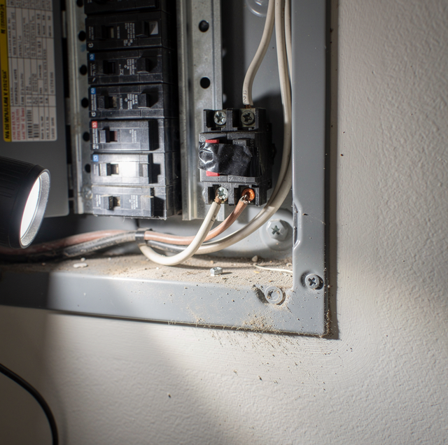
Ten pages into your home inspection report, one line reads "double-tapped breaker, panel position 14," wedged between a note about caulk at the tub surround and another about the water heater strap. Nothing in that sentence says whether position 14 is a five-minute fix or a reason to slow down before closing, and the panel gives no clue from the outside; the cover is closed, the house has power, nothing looks wrong. The gap between those six words on the page and what is happening at that one screw is where you're standing right now, trying to work out how alarmed to be.
One Screw, One Terminal, Two Wires
A single-pole circuit breaker has one terminal: a small clamp consisting of a metal plate and a captive screw, designed to press down on a bare copper conductor seated in a slot below it. Turn that screw, and the plate closes on whatever sits under it, whether that is one wire or two. A double-tapped breaker is exactly that: two separate circuit conductors, usually feeding two entirely different circuits in the house, squeezed under the same plate and held by the same single screw. Nothing about the breaker changes size or shape to accommodate the second wire. The terminal built for one conductor is doing the same job with double the metal crammed under it.
Why One Screw Can't Grip Two Wires Evenly
A terminal screw is torqued to a specification written for a single round conductor of a known diameter filling the slot underneath the plate. Two wires do not fill that space the way one does. When round wire is pressed against round wire, a gap forms between them, and the plate coming down on both at once tends to bridge that gap rather than seat flat on either conductor. One wire typically carries most of the clamping pressure, while the other sits only loosely trapped, held in place more by friction than by a true clamp.
The mismatch gets worse whenever the two conductors are not identical. A 14-gauge wire feeding a lighting circuit and a 12-gauge wire feeding an outlet circuit have different diameters, so a torque setting correctly for the thicker one leaves the thinner one under-clamped from the moment the screw is tightened. Solid wire and stranded wire behave differently under the same pressure too. Stranded conductors compress and settle as the strands shift against each other, while solid wire holds its shape, so pairing the two under one screw means one keeps changing slightly after the other has already stopped moving. None of these combinations produces a clamp that holds both conductors the way the terminal was built to hold one.
Heat at a Joint the Breaker Isn't Watching For
A breaker's job is to monitor the current flowing through it and trip when that current exceeds what the wire behind it can safely carry. That is the entire function of the thermal and magnetic parts inside the breaker body. A loose clamp does not add current, and it does not by itself push either circuit over its rating. What it changes is how well two pieces of metal actually touch.
Current forced across a poor contact behaves the way it does at any weak connection: some of that energy turns into heat right where the metal barely meets, because a marginal contact resists the flow of current more than a solid one does. That heat comes from the joint itself rather than from either circuit pulling more current than it should, so it does not show up as the overcurrent a breaker is watching for. The thermal half of the trip mechanism is a bimetallic strip that bends as it warms, and heat conducted in from a bad terminal can eventually bend it far enough to trip the breaker, which is why loose lugs turn up as a cause of unexplained tripping. That usually happens late, though, after the joint has been running hot long enough to do its damage. So a double-tapped breaker can sit for years with both circuits running well under their rating, tripping normally on any real overload, while the joint under the screw runs warm on ordinary use and works on the insulation and the breaker body around it a little more each time. A breaker that has never tripped tells you nothing about how sound the connection under its screw is.
Treat a double-tapped breaker as a heat problem even if it has never tripped. Leave the panel cover on; an electrician checks the terminal and the surrounding insulation for heat damage, then separates the two conductors.
A Finding to Verify, Not a Verdict
Not every breaker terminal is built to hold only one conductor. A number of breaker models on the market have terminals listed to accept two conductors, within stated gauge limits, and that listing is printed directly on the breaker itself, usually near the terminal, rather than buried in a manual somewhere. On one of those breakers, two properly sized wires landed under the screw are exactly what the hardware was built and tested to hold.
That is why "double-tapped" on an inspection report describes what the inspector saw: two wires under one screw. Whether that is also a problem is a separate question the phrase alone does not answer. Confirming whether the terminal in question is one of the listed kind, and whether the wires actually seated match what that listing allows, is a separate step from noting the two wires in the first place. Whether a given panel and breaker combination passes on that basis is the inspector's and the local electrical authority's call.
This is not something to sort out by pulling the panel's cover off yourself. The dead front comes off to expose the main lugs and the bus, both of which stay live at full service voltage even with individual breakers switched off, and reading a terminal's listing correctly is exactly the kind of close, careful check an inspector or electrician does with the right tools and the panel open under controlled conditions. Your part is knowing what the words on the report mean; confirming them at the screw is the responsibility of whoever is doing the check.
Two Ordinary Ways a Panel Runs Out of Room
Two ordinary situations put a second wire under that screw, and neither is about the quality of the original wiring job.
The first is a circuit added after the panel was already full. Someone, an electrician working quickly or a homeowner comfortable with a screwdriver, needed to land a new circuit and found no open slot waiting. Rather than stopping the job to properly resolve that, the new wire was run under an existing breaker screw alongside whatever was already there. The second is a panel that has simply run out of physical space for the number of circuits the house now needs. A finished basement, a workshop, an added appliance circuit, each one landing somewhere over the years, until the slots ran out well before anyone stopped needing new circuits.
Both situations end at the same screw for the same reason: a circuit needed a home, and the panel did not have an open one waiting when it did.
The Fix: Pigtail, Tandem Slot, or Subpanel
Once an inspector or electrician has ruled out a listed exception and confirmed a real double tap, the fix comes back to the same principle: giving each conductor its own clamp. Which repair fits depends on what your panel has room for.
A pigtail is the most common repair on a single overcrowded terminal. An electrician joins the two original conductors together with a proper connector inside a junction box or the panel itself, then runs one short new wire, the pigtail, from that joint to the breaker's terminal. The breaker still clamps only one wire; the two original circuits are now spliced together upstream of it, in a connection designed to accommodate more than one conductor.
Where the panel has an open slot rated for it, a tandem breaker can split a single-pole position into two independent breakers, each with its own terminal and trip mechanism. This only works in slots the panel's manufacturer has specifically listed for a tandem, marked on the panel or in its documentation; forcing one into an unlisted slot trades one clamp problem for a different mismatch entirely.
When the real issue is that the whole panel has no slots and no tandem-rated positions left to give, the fix stops being about any single breaker. Whether that calls for a subpanel or points toward replacing the panel is its own sizing question, separate from the clamp itself.
Weighed against the rest of your inspection report, a double-tapped breaker sits in the middle of the list: worth resolving before or shortly after closing, alongside something like a missing GFCI or an ungrounded outlet, well below exposed wiring or a scorched panel cover, which get flagged for the same day. How long that clamp has already been running warm, if it has been running warm at all, decides the real urgency more than the date printed on the report.
Frequently Asked Questions
Neither, in the way "broken" usually means. The breaker's trip mechanism, the thermal and magnetic parts that sense current and pop the handle, works the same whether one wire or two sits under its terminal screw. The fault sits at the clamp, separate from the breaker's switching mechanism. Swapping in a brand-new breaker without changing how many wires land under it reproduces the same problem on the replacement, because the new breaker's terminal has the same single-conductor geometry as the old one.
It can, but the rule is different there. Many neutral and ground bar terminals are listed to accept two or more conductors under a single screw, a different design than most breaker terminals use. A "double-tapped neutral" finding calls for checking that specific bar's printed listing rather than assuming the single-conductor rule that applies to most breakers carries over automatically.
A multi-wire branch circuit, which shares one neutral between two separate hot legs, uses a two-pole breaker, with each hot conductor landed on its own terminal rather than two wires sharing one screw. Seeing two wires enter the panel near each other is not the same thing as finding two wires clamped under a single terminal, and confusing the two is an easy misread from a quick look.
For ordinary overcurrent, yes, since that is a separate measurement from the clamp's condition. Arc-fault protection leaves the same gap open. An AFCI breaker is built to sense the electrical signature of arcing out in the branch-circuit wiring downstream of it, while a degrading terminal clamp more often becomes a glowing high-resistance contact than a true series arc, and the joint sits at the breaker's own load terminal, the least favorable spot for that breaker to sense anything at all. That protection earns its place on its own merits, and it should not be relied on to handle a bad connection at the breaker's terminal.
Not necessarily. Copper expands and contracts with every heating-and-cooling cycle a circuit goes through under normal use, and a clamped joint slowly relaxes under that repeated movement, a creep and stress-relaxation effect far more pronounced in aluminum but present in copper too. So a clamp that held tightly on installation day can lose grip years later, on its own schedule. A long stretch without a visible symptom is a description of what already happened, and it says nothing about how tight that clamp is right now.
The marking is only half of it. A terminal listed to hold two conductors generally carries the condition that both wires be the same gauge, so a breaker rated for a pair of 12-gauge conductors still rules out a 12 and a 14 sharing the screw. That same-size condition is what most field double taps fail, even on hardware that permits two wires, so the check comes down to the gauge stamped on each conductor's jacket as much as to the wording printed on the breaker.
Get a double-tapped breaker fixed properly — an electrician checks the panel and corrects the terminal your inspection report flagged. Safeline Electric serves Vancouver, Camas, Battle Ground, and the surrounding Clark County and Southwest Washington area. Call (360) 505-0663.
